Using the Raspberry Pi as an Oscilloscope
An Oscilloscope is right up there next to the DVM as a must have tool.
I've used a Hung Chang HC-L202 20MHz Dual Trace that I managed to "rescue" from someone around 15 years ago. It's not portable and being analogue it's only good for repeating signals. No chance of debugging signalling or data (like I2C).
Ever since reading an article in Everyday Electronics (October 1991) about a PC based ocilloscope I've wanted to do this. The EE article used a CA3306 and showed samples up to 1MHz. [I've reproduced pages 620-626]
I've attempted a PC scope a a few times, but the outcomes were insufficient (using ADC0804's (slow), and manually clocking the CA3306E using a 555 timer (still couldn't read the ADC fast enough). Nothing where NEAR the Mega Samples per second needed to start looking at signals above the audio range.
I'm not serious enough about having a Digital Storage Oscilloscope that would buy one.
A few months back I saw an article in the MagPi - Issue 24 - also mentioning the CA3306E and sampling @ 10MHz and a kernel driver to read it. I built that, but there was no display solution.
The kernal module meant interrupts could be disabled so sampling the ADC around 10MS/s is indeed possible with this ciruit.
This page from the National Instruments (NI) website is an excellent read. For years I've been annoyed at the Nyquist theorem - it a good case of a true fact, but not the whole truth. From the NI page - "sampling at just twice the highest frequency component is not enough to accurately reproduce time-domain signals.
Based on the information from above @ 10MS/s frequencies up to 3MHz should be do-able. This works for me.
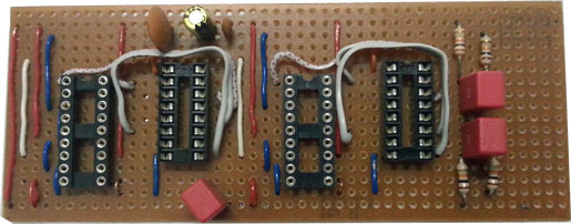
The Everyday Electronics (although more than a decade old) explains the CA3306 IC very well and the The MagPi article explains the circuit used. It's clean simple and it works.
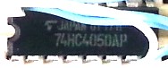 My only deviation was to use a 74HC4050AP rather than a TXB0108. It's cheaper, simpler to use and there is no need for the RPi clock line to be converted to 5v. The ADC will clock just fine @ 3v.
The solution contemplated here
- Uses a CA3306, a flash ADC, (read the wikipedia artice on ADCs) capable of 15 million conversions per second. It is, however, only 6bit so that's a 64pixel high waveform.
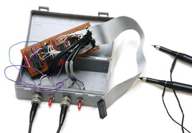
- Reads the output using the Raspberry Pi's GPIO pins
- As Fast as it can, plotting the values live, around 500kHz
- Using a Kernal driver (from the MagPi Article) that suspends interrupts and clocks the ADC @ 10MHz and reads the values to a temporary structure.
- Displays the resultant waveforms directly on a memory mapped framebuffer.